Set the temperature
for your session.
Far-infrared heating warms the mineral surface, with digital temperature control on heating-equipped models.

Technology / Product engineering
Pulsed electromagnetic field (PEMF) coils, infrared heating, red / near-infrared light and mineral surfaces. Explore each system and the layered construction, then define the specification for your branded mat.
Discuss a technical brief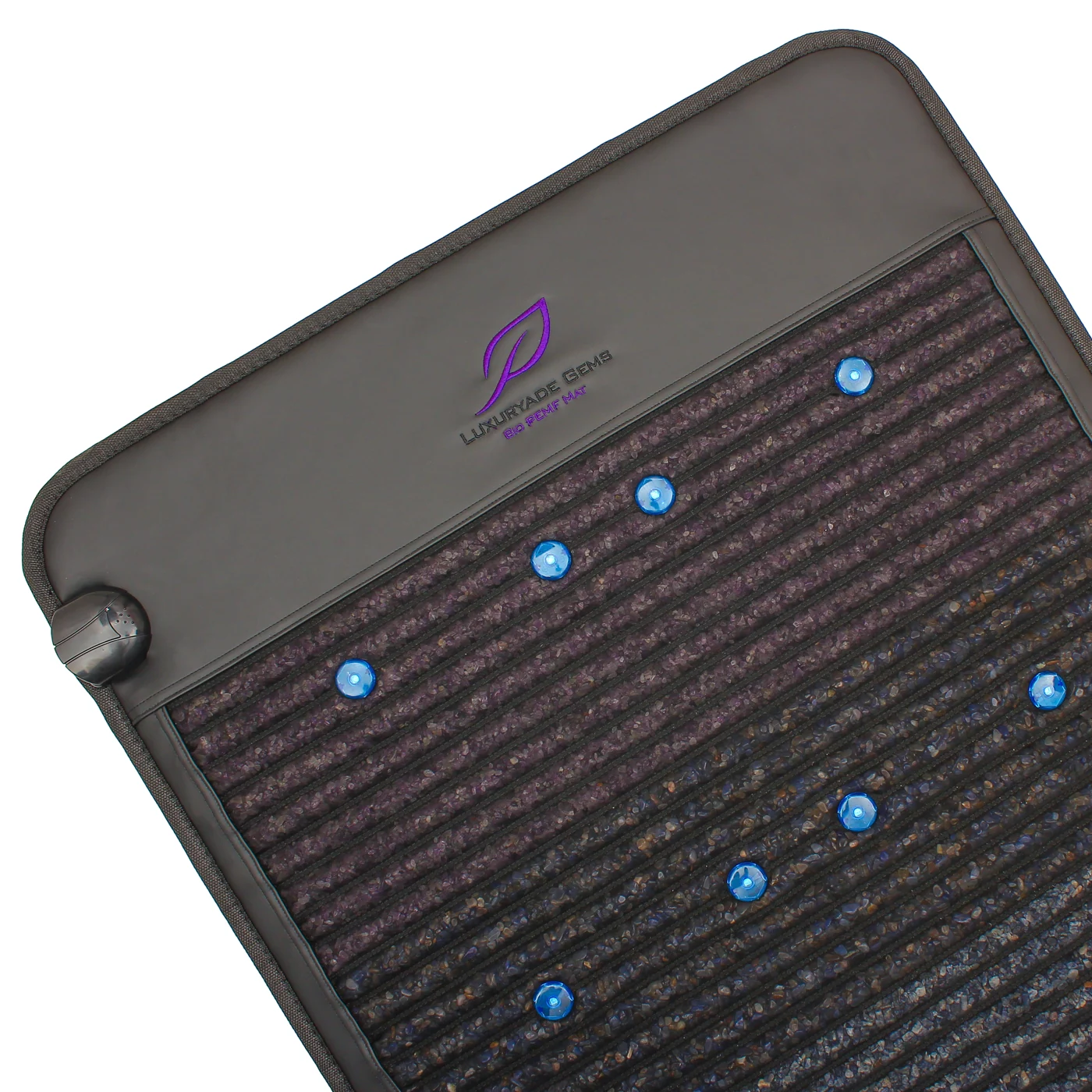
What the product offers
Create a comfortable place to pause with adjustable mineral-surface heating, selectable PEMF programs and integrated light options. Our range brings these features into full-body mats, compact pads, belts and pillows.
Far-infrared heating warms the mineral surface, with digital temperature control on heating-equipped models.
Integrated coil systems bring PEMF into full-body mats, compact products and selected pillows and belts.
Choose a red-light or dual-band platform with LEDs arranged across the mineral surface.
Applications / Match the product to the setting
Full-body mats, compact pads, belts and cervical pillows give brands a choice of formats for different spaces and ways of resting.
A quiet break, evening wind-down or seated rest. Choose a full-body mat for reclining or a smaller format for a chair or personal space.
A place to rest after training, at home or in a gym recovery corner. Compact and full-body formats suit different floor plans.
Mat-based wellness sessions on a suitable table or resting area. Protective covers and accessories can be included in the project.
Compact mats, belts and cervical pillows complement the full-body range, with controls and dimensions suited to each format.
Construction / Surface to base
The exploded view shows the mineral surface, support materials, heating assembly, protection parts and PEMF coils. Follow the numbered groups alongside the drawing.
Synthetic PU leather forms the exterior frame. The reference shows an embroidered logo; the color, finish and logo placement are part of the OEM brief.
The reference construction labels a 660 nm red LED layer. The final light board, quantity and any 850 nm NIR option are specified by model.
A mesh layer sits over the mineral surface. Mesh density, retention, stitching and the finished contact surface are checked on the sample.
The illustrated version uses eight gemstones. Other catalog platforms use amethyst, jade, tourmaline or seven-crystal arrangements; the composition is a separate specification.
A cotton layer containing charcoal material sits below the mineral assembly. Its thickness and placement are part of the construction specification.
An Oxford fabric layer separates parts of the internal assembly and supports the layered mat construction.
A dedicated isolation layer is identified in the reference assembly. Specify its material, coverage and relation to the heating and coil systems in the production drawing.
A conductive foil layer is included in the shielding and heat-spreading construction. Coverage, joints and insulation are checked with the electrical assembly.
The electrical heating element is integrated below the surface assembly. Rated power and element distribution change with the dimensions and electrical version.
The reference specifies silicone and fiberglass in the heating-wire construction. Wire routing, fixation and bend areas are included in the assembly specification.
The probe provides the temperature input for the controller. Its location, contact and connection are defined for the selected heating assembly.
An automatic thermal cutoff provides overtemperature protection within the heating assembly.
Two layers of high-density nonwoven material support the heating assembly. They hold the selected element layout within the layered construction.
The reference identifies fiberglass and aluminum-foil materials in this insulating layer. The placement and separation from conductors belong in the construction drawing.
A second cotton / charcoal layer appears below the heating support. Its thickness contributes to the assembled profile and handling of the mat.
Coil modules are placed within the lower assembly. Quantity, module positions, fixing and cable routing are specified for the chosen mat or accessory format.
Compressed cotton provides a supporting base within the assembly. Density and thickness are defined with the weight and overall profile of the product.
The underside closes the mat construction with a wear-resistant fabric or selected exterior material. Seams, finish and the final label placement are checked before packing.
01 / PEMF system
Integrated coils and digital program selection bring PEMF into full-body mats, compact formats and selected accessories.
Nine selectable programs on our standard PEMF platform.
Copper windings, laminated silicon-steel cores and electronic control form the PEMF system. The coil arrangement suits the dimensions and construction of each product.
PEMF / Coil architecture
Coil modules sit within the mat’s layered construction. Their arrangement follows the product’s dimensions, shape and controller system.
Copper wire is wound around laminated silicon-steel plates to form each coil module. Electronic switching drives the coil system according to the selected PEMF program.
Preset or mixed mode
Operation of the coil system
Modules within the mat
Full-body, compact and accessory products use different coil arrangements. OEM development can address module placement, fixing, connectors and cable routing together with the mat structure.
A small magnetic indicator provides a visible demonstration of PEMF operation when used with the coil system.
02 / Infrared heating
The heating element, mineral surface, temperature controls and timer are developed as one assembly.
Electrical power varies with the format: A010 uses 55 W, A030 uses 100 W and A063 uses 300 W. Voltage versions are specified for the delivery market.
Heating-wire preparation and integration within the mineral mat. The factory’s equipment includes semi-automatic heating-wire lines.
Sensor, controller and heating response are reviewed with the selected structure. The temperature range belongs to the individual platform.
A and LK platforms offer 110–120 V or 220–240 V versions, with plugs and product labels for the destination market.
Review the heating controls, timing, surface finish and operating instructions on the approved sample.
Heating / Control & protection
The selected operating temperature, the sensor input and the overtemperature protector each have a distinct place in the construction.
Resistive heating wire is routed and held within the assembly. The reference identifies silicone / fiberglass wire construction and double nonwoven support. Element layout and power are matched to the format.
A-series examples: 55–300 W by modelThe temperature probe is the controller’s input. Specify its position, connection and contact with the assembly, then evaluate heating response on the selected sample.
A & LK control range: 30–70°CAn automatic thermal cutoff protects the heating assembly against an overtemperature condition, alongside the temperature probe and controller.
Automatic thermal cutoffThe approval brief should state the voltage and rated power, heating-wire drawing, probe position, controller temperature range, timer, protector part and relevant test conditions. A controller setpoint and a component cutoff rating describe different parts of the system.
03 / Integrated light
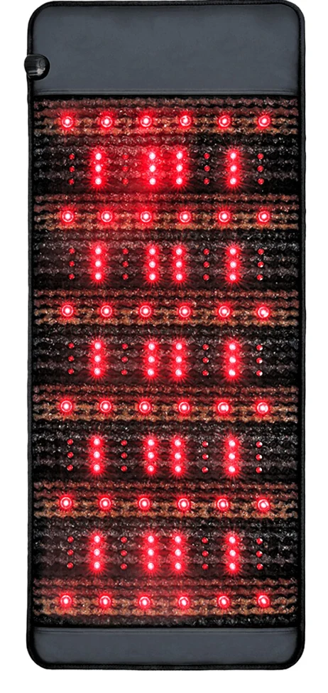
A product’s LED configuration should be explicit. Red-only and dual-band platforms are kept separate throughout the catalog.
Dual-band platform comparison
The counts below are listed in our June 2026 standard catalog and A-series specifications.
Materials / Insulation & shielding
The reference structure identifies an isolation layer, aluminum foil and insulating reflector materials. These are part of the electrical and thermal assembly.
The product brief should name the material, thickness, coverage and joints, together with the separation from heating wire, coil wiring and the exterior. The finished product’s electrical classification and test documents are checked for the selected version.
Define the isolation material and its position relative to the electrical components. Keep the layer specification tied to the actual assembly drawing.
Foil layers, joints and insulated wiring form part of the layered construction. Electric-field shielding and the intentionally generated PEMF magnetic field are separate characteristics.
Specify the fiberglass / foil construction and its role in the heating stack. The insulation and reflector layers form part of the heating assembly.
Optical & thermal systems
Red and near-infrared LEDs combine with the mineral surface, while the heating assembly provides adjustable warmth. Choose the systems that suit your product range.
The red-light configuration uses LEDs installed in the surface assembly. The technical brief defines 660 nm; catalog models specify the quantity and placement.
Red-only B / BR configurationsSelected platforms add 850 nm NIR alongside red LEDs. Keep the red / NIR split explicit in the bill of materials and controller specification.
Dual-band A-series configurationsElectrical heating warms the mineral surface. Digital controls let users select the operating temperature on heating-equipped platforms.
Heating and combined LK platformsFrom LED count to an assembled product
The Gems Mat reference highlights the challenge of integrating 156 or more LEDs. A finished mat must connect the light positions with the mineral layout, mesh, wiring and outer construction.
Define each light position and how it sits within the mineral arrangement, mesh and cover.
Specify the board or module, connectors, cable routes and retention within the layered assembly.
Identify the light selections, indicators and which functions can be operated independently on the selected controller.
Compare the actual wavelength configuration, count and placement with the approved specification and check the selected light operation.
Heating and integrated LEDs are separate product systems. Red-only and red / near-infrared versions are available across the range.
04 / Controller & electrical platform
A clear interface is part of the product experience. Controller functions, labels and accessories are specified alongside the mat.
Function architecture / selected platforms
Temperature + timer
Program + coil system
LED layout + selection
Accessory + output
Function architecture, rather than a wiring diagram. The available functions depend on the selected platform.
The B, D, K and T catalog materials show MCU-2 controller and TENS configurations. The A and LK sheets define their own combinations of heating, PEMF and photon light.
TENS is an electrical-stimulation option on selected platforms. It is specified separately from PEMF coils and light modules.
Define your controller requirements05 / Natural minerals & ceramics
Color, texture, particle form and mineral arrangement give each family a different appearance. The approved material sample anchors the production specification.
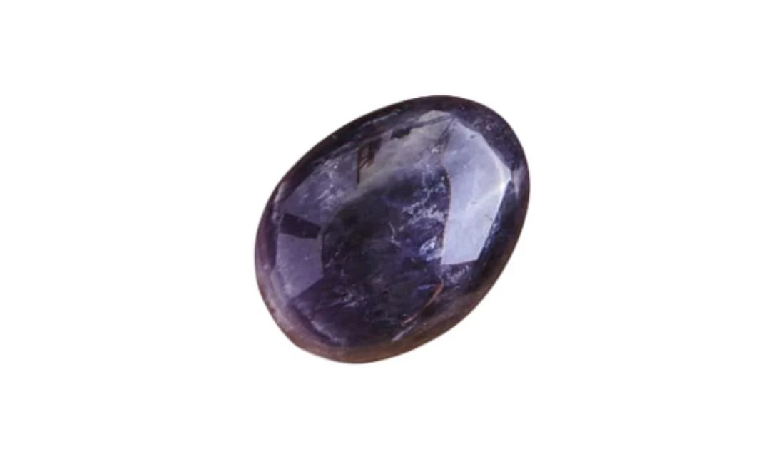
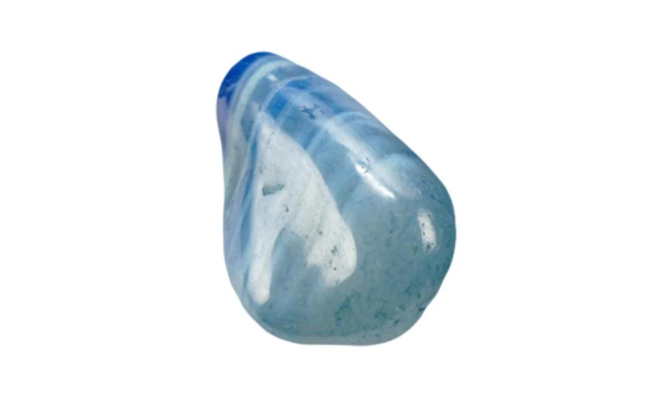
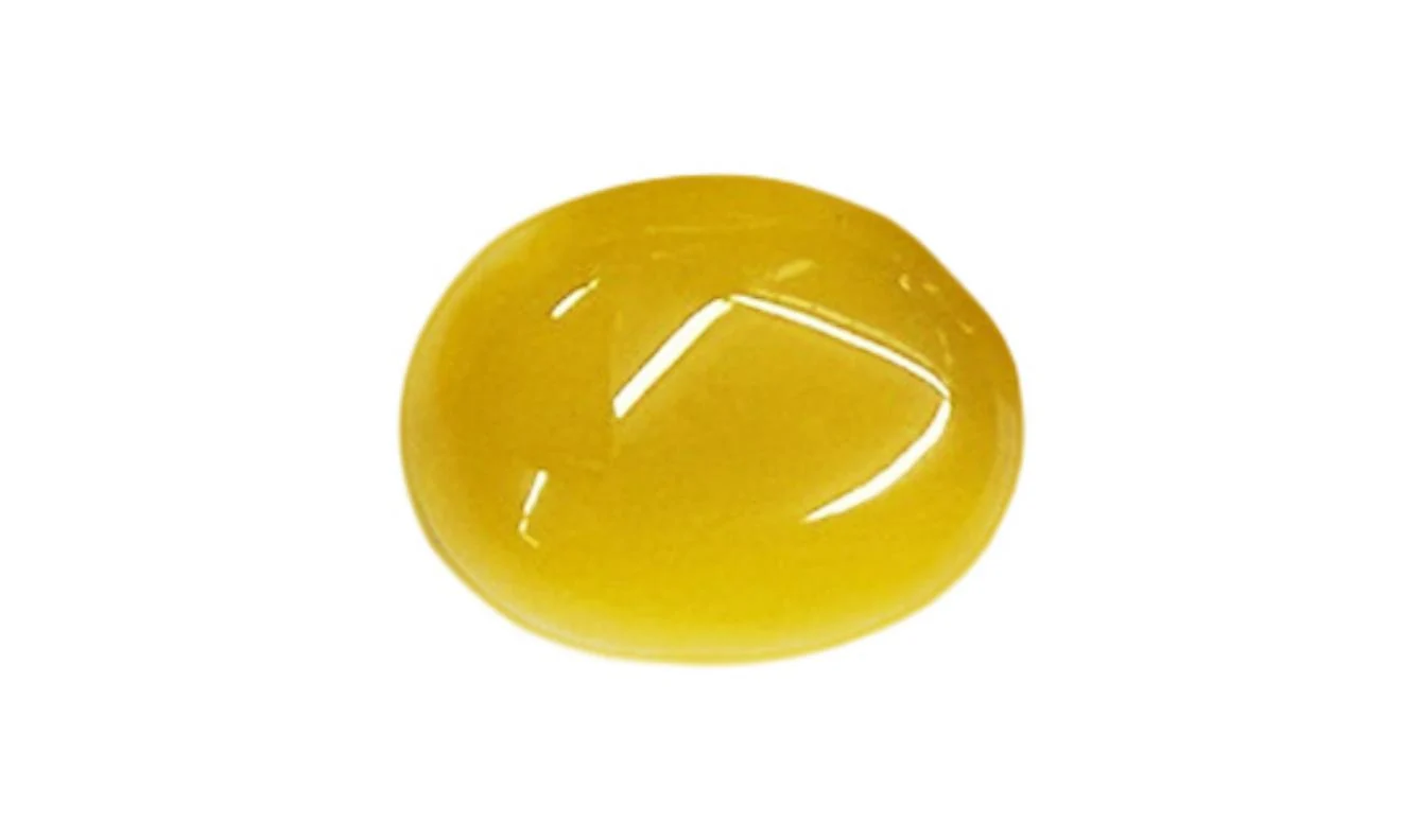
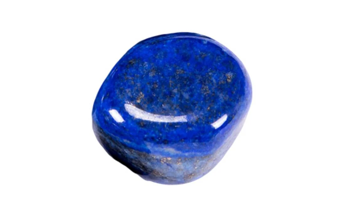
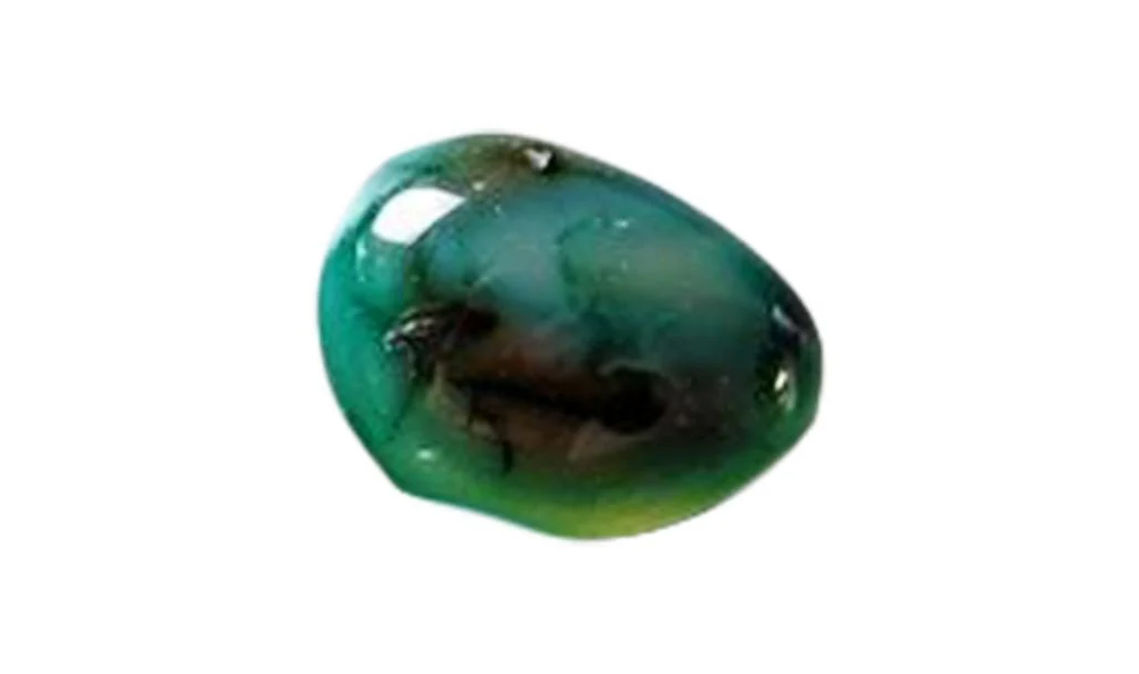
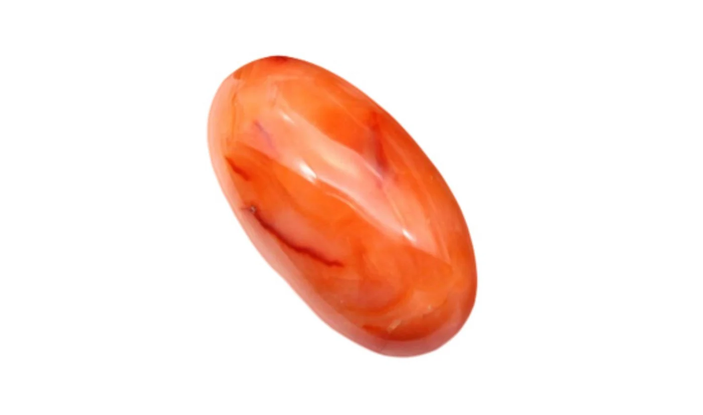
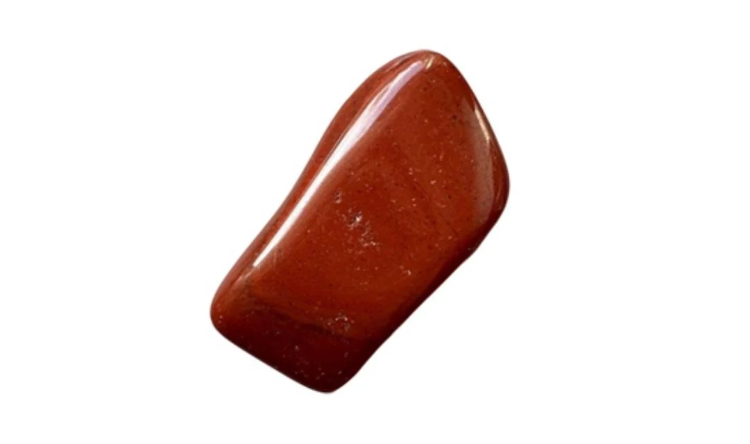
A, B and crystal platforms use mineral textures and multi-color arrangements. Specify the stone selection, particle size, proportion and surface layout.
Seven-crystal rangeThe standard collection includes jade and tourmaline combinations. A2601 uses green jade with tourmaline; A2603 uses black jade with tourmaline and RGB light.
Crystal & jade collectionK, T and LK materials include ceramic mineral components. The technical material descriptions list blends such as tourmaline, germanium, jade and volcanic minerals by platform.
Tourmaline platform rangeMaterials / From mineral selection to production
A mineral name does not describe a complete mat. The proportions, physical form, arrangement and retaining construction give the surface its finished identity.
E2609 lists 50% amethyst and 50% black tourmaline. E2607 combines 35% amethyst, 23% mixed gemstones and 42% black tourmaline. The material mix remains tied to its individual model.
Explore the E2607 mixCrystal particles, jade pieces and mineral ceramics create different surfaces. Agree the mineral selection, piece dimensions, proportion and layout together with the LED positions and mat format.
Compare crystal & jade surfacesMesh, stitching, cover materials and the outer frame support the visible mineral arrangement. The reference construction also includes cotton, nonwoven support and compressed-cotton padding.
See the construction componentsUse a material sample, composition list, layout drawing and finished surface sample. Include the intended dimensions, profile and weight target so changes in material quantity are evaluated with the complete product.
06 / Build your technical brief
Format, dimensions, weight target, outer material, mineral selection and surface arrangement.
Heating range, PEMF programs and coils, wavelength, LED count, timing and optional TENS.
Logo, color, controller interface, accessories, carry bag, instruction manual and retail packaging.
Destination, voltage, plug, documentation requirements, sample plan and initial quantity.
Technical questions
No. LED quantity, wavelength, physical distribution and controls are separate specifications. A red-only mat and a red / NIR mat with the same total LED count are different configurations.
A and LK heating platforms provide adjustable 30–70 °C control. Temperature settings and timer functions are operated through the digital controller.
Yes. B and BR, and K and KR, are separate catalog configurations. For example, B190 lists 156 red LEDs while BR190 lists 72.
Coil layout is reviewed with the dimensions, construction and controller. Standard models provide a starting point; a custom layout needs a development review.
Ask for the selected model specification, controller instructions, electrical rating, sample configuration and applicable product test documents.
Send the dimensions, materials and functions your brand wants to develop.